Sunday 20 July 2014

RETRO BUILD: AMT/ERTL Galaxy Class Tesla (Enterprise-D) Part 5

Hello again, this is another retro build of an old AMT USS Enterprise D from 'Star Trek Generations' (TNG).  For those just seeing this for the first time, I'm posting about a build I did for a good friend of mine as a gift last year.  On with this post entry...

STARDRIVE SECTION (Engineering)

Again, the methodology for building this model has been in sections but also to built around an internal structure made of plate aluminum and a bent threaded rod.  Taking a cue from the 6' studio model, I cut some whole parts in sections so I could better attach it to the armature.  Also, a thing to remember is the Enterprise D is actually 2 ships, joined together - the saucer section and the the battle section or 'stardrive' which is what I'm focusing on.

Starting the assembly of the wiring.  I glued styrene to both sides of the aluminum plate so I can mount a wiring harness to it without shorting the circuit.


And this is the first time I used this technique, something which is common to all of my builds when I need to have a parallel circuit, a 'bus bar' made of AWG 14 copper.  Least resistance for electrons to flow, especially at 12V DC (which this model is).


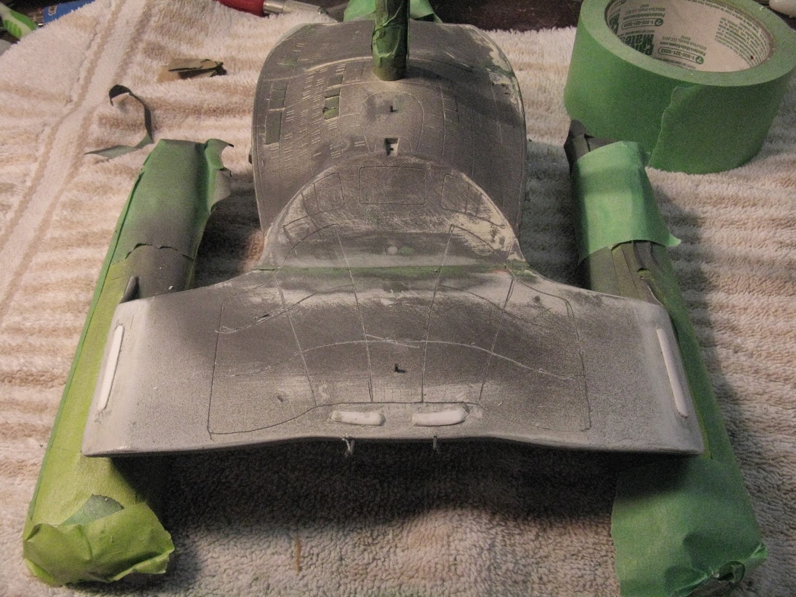
For the bottom of the engineering hull, I cut the part into 3 pieces: a forward section around the deflector, a middle section which is the engineering section, and the aft end which is solely the nacelle pylons/struts,  Here is the middle section.  The advantage of doing it this way is to have a section which is separate of the main components so I can do final wiring with most of the model sealed. 


Assembly of the Warp Drive section to the Engineering Hull...

My original plan was to mate this component to the engineering hull with screws and use the whole upper engineering hull as a guide.  Reality dictated something else.  I planned this out very carefully using the lower (mid section) of the engineering hull as a guide.


I didn't shoot the engine assembly, but it go painted a 'duck egg' blue.  I then mounted it to the armature using hot glue, lots of hot glue. And after letting it cure for a few days, good luck getting it apart!

Here's the whole model lit up, starting to look like something familiar...


The final hook up for the warp nacelles are all the fiber optics I put in there.  I learned some very hard lessons, one of them is Testor's model cement (both tube and liquid form) eat fiber optics and using a heat gun with shrink tube is a very, very bad idea.  Since then I've watched what other pro-model builders do and they sometimes use brass tubes, which is what I've started to do since this build, so I can correctly aim the lens of the LED to the shaft of the fiber optic.  The tricky part of this was drilling almost flush to the edge of the model to have dual red/green nav lights at the stern of the ship.  I built up the thickness of the struts which made this process easier.


Once I completed this part of the model, and was satisfied everything was wired up, I glued and sealed the remaining engineering hull segments.  Lots and lots of Green Squadron Putty.  (Today I used 3M Glazing Bondo #3 - half the price, twice the size, aka 'red putty').


The spikes are the fiber optics which will be cut flush to the hull.


Now that I have a smooth surface, I can put back the details I removed, like the Phaser Banks.


The Phaser Banks on the curve of the struts were always in the wrong place.  Using the plans online of the studio model and pictures from the Christie's Auction, I could accurately place them on this model.


The row of styrene is to cover the seam, and this is a detail on only the 6' model which is used to...cover a seam.   


Once everything was smooth, I painted the remaining details (this is how I used to build models, paint the details, mask them, then put the base colour down - it sometimes leaves paint build-up so I generally do the reverse with a few exceptions) then masked them.


Then I returned to finish the remaining Aztek markings on the engineering hull.


For the lower section, I used set of decals available on Starship Modeler by Arthur Pendragon but in this case turned them into masks.  Pretty low tech, I used Avery removable full sheet labels.  They did the job without leaving a residue (for the most part) behind.  I tried to not leave them on the model too long.


Here is the second colour, white.  In doing a few tests, I found I could layer colours for effect depending on the base primer, this is what I'm doing here. 


 Now for the third colour, metalic silver.


Finally the hull colour which is a duck-egg blue.  The silver effect is there but barely visible.


So next time, I will be covering the saucer section, lifeboats, lots of lifeboats and more Azteks. 

Happy model building and check out my latest build, USS Defiant as seen in 'The Tholian Web'.

Wednesday 16 July 2014

AMT/ROUND 2 USS DEFIANT as seen in 'THOLIAN WEB' 1/650 scale Update #2

Greetings...

It's been about a month since I last posted...been pretty busy since the start of July on other freelancing projects and leading up to the end of June, I've been busy with this model.  So this is a semi-big update.  What I mean by that is two of the main sections are assembled (minus a few details) and the electronics are in - which was a learning experience...

This model is both charming and frustrating...Why?  It's grand nostalgia for anyone who built this kit before, and I built many of them as a kid.  Frustrating as I soon learned that cutting into the model seems to break up the 'glow in the dark' feature, so I have to go with less modification, which will make it easier but very inaccurate.  I digress.

After building the structure for the stand, the first thing I wanted to check is to see the interaction between the black light and the model itself.  Also if the foil did anything to amplify the black light.  My plan is to have a mirror finish on the bottom of the base. 


I'm using a standard, threaded rod, commonly used in lamps and hanging light fixtures.  The advantage to this is a secure base, the disadvantages are it looks rough (I have a brass rod to cover it) and the internal diameter is somewhat small.  It works perfectly for this model.


The clear 'tray' is for the wiring distribution harness.  Normally I glue it to the model but since this is very translucent, I decided the best idea was to suspend it to diffuse any potential shadows.


Here is the rest of the model mocked up being held together by only tape.


I have also pre-drilled all of navigational lights on this model (which you can just barely make out above).


The neck - the problem with the neck (aside from being the wrong shape in terms of a horizontal cross-section) the forward edge does not meet the saucer.  Since this does get painted, I can fix it.

I used tape to prevent any putty getting on the hull surface.


I filled the gap with first styrene, then Evercoat Metal Glaze.  From there it trims to shape after 20 min and cures within hours.


Next I installed the wiring into the lower secondary hull.


Sanded and smooth, time for painting the leading edge of the neck.  Since the plastic looks white in daylight/office light, I decided to use lighter accents, such as the hull colour for my 1/1000 USS Enterprise for the lighter accents and slightly darker shade for the primary accents,  I also used white primer instead of standard gray which fear may cause shadowing within the model.


At this point, I had a pretty big decision to make: assemble the sub-assemblies first then glue them to each other or, glue the upper engineering hull/neck to the lower saucer.  I chose the later (and it was a goo thing too).  It just so happens that the distance between the bottom of the saucer rim and the centre line of the engineering hull is 2 inches.  Made for easy alignment.


Assembly of the engineering half went together quickly and it was easier (and neater) pulling the wires through the assembled neck/lower saucer than it would have been gluing them up as 2 units and then aligning them (headache avoided).


The next decision was to improve the deflector dish assembly.  It is horribly inaccurate.  The dish is too deep, lacks details and sticks out too far.  The deflector housing's concentric rings are stepped and not deep enough.  A scratch built one is in order!


One thing I find useful is having a collection of old parts, in this case 1/1000 deflector dish 'pilot version' from my last Space Seed Edition model.  It is a similar size to the kit dish.  Combined, not a bad substitution - easier than building my own, and less costly than ordering an after market part.


To build new rings, some brass/aluminum rod tubing and a left over nacelle from the same kit (dating back to the early 90s).


And carefully, carefully removing the old center section...


I put a backing on the deflector housing so I can glue the ring assembly straight to the ship.


Early on, I scanned in the decals and some 1/350 parts to this scale, 1/650 so I can use them as templates for add-on details such as the raised lines on the side of the engineering hull and the trapezoid detail just fore of the TOS Starfleet Pendant.  It was also helpful in locating the p/s beacons at the aft end of the engineering section.


The gap will be mostly covered with the trapezoid piece of styrene.  Normally I'd fill this but since I can't paint it...but I can paint the ribs, a pale gray.


The trapezoid section:


Saucer top: I drilled out the holes on both top and bottom Bridge and Sensor domes, the holes for the navigation beacons and finally built a new 'linear accelerator' (that's what I've heard it called) on the dorsal area of the saucer where the neck connects.  In reality on the 11' studio model, it covers the bolts which attach the saucer to the neck.  Makes sense.


This was my first model building attempt to cast clear resin parts from existing parts.  I used the clear bridge dome from a 1/537 AMT Cutaway USS Enterprise (good scale, some very wrong details and the cutaway portion is very crude) released in 1996. 


To make the mold, I used 'Mold Builder' which I got a local craft store which is a latex, paint on mold making.  The instructions say to put 8-12 coats on it with gauze bandages as a stiffener.


For the resin, I'm using a 2 part clear resin, from the same hobby store.


Since I'm casting a small part, I've made good use of looking through future builds which will require clear or replacement parts I've lost. 


Giving it 24 hours to cure it's still bendable and if you're not careful, you can leave finger prints on it (found that out the hard way).  For the bridge dome, I was able to friction fit it while it could still bend and sculpt the top.  For the lower dome, I waited an extra few days do I could flat sand it to fit.

ELECTRICAL

The saucer has most of the lighting in this model, p/s red/green nav lights, p/s red/green fiber optic, constantly on, flashing nav's on the lower saucer, aircraft warning light on either side of the bridge and both clear domes I cast are illuminated. 


Again, I made a neat tray for the wiring to rest upon which I frosted so as to not create shadows within the saucer where all of the wiring would connect.


As an aid in building this, I taped together the warp nacelles so I could leave 'the lid flipped open'.  Easier to wire this way, and another reason I prefer to not seal up the saucer if I'm lighting it.


Since I'm using an odd power supply, 6.3 Volts, 400 mA, I discovered I have way too many little lights, particularly the strobe couldn't drive all of the LEDs  I had on it so I decided to rip out most of the resistors and add a second strobe light.  That did the trick after many evenings and many 'adult' drinks.


I found out the hard way, with a translucent model, and clear plastic mounted inside, the whole model became one big fiber optic.  What I had to do was to light block each bulb, aside from the direction they are aimed at to control the light.  Aluminum tape and Tulip black fiber paint.  I also learned this would be a great model to light internally as the plastic is almost white and using bits of tape to mark windows, you could light the whole inside, light block from the front and have the model glow - an idea for the future, maybe even a kit-bash...I digress for now.


And now finally closed up tight.  Lights work perfectly and although I should have taken more pictures of the of the model lit with the blacklight on it, I can honestly say it works very well.


More to come, finishing off the saucer details, the deflector array, and impulse engine.  Then the warp engines...since the model is caught in a Tholian Web, I decided to not have fancy lights in the nacelles front domes, but an interesting idea to create static rotor blades.

Happy model building and stay tuned for an update soon!

Cheers!